
Is GaN worth it?
There is a buzz in the industry about the benefits of GaN. Better performance, higher efficiency, more compact? Let´s have a look.
Learn More
Background
GaN switches offer a theoretical advantage due to the smaller charges and/or low ON-resistance. You can get half the ON-resistance and approximately 30% less output charge in a very tiny package with almost negligible gate charge. But the littleness of the device also proposes challenges as it becomes very difficult to measure the die temperature in an accurate way. And if the amplifier cannot be protected from overload or short-circuiting, it can´t really be used in real life.
There is also an opportunity to make smaller amplifiers as the lower charges allows for a higher switching frequency which in turn allows for smaller inductors in the output filter. This also goes well with the research we have performed on loop designs with high fsw.
In this article we will focus on the technical advantages and continue to work on how to make the amp robust once we proceed to a product development.
The Test Subject
We are using the 2x300W Conductor amplifier topology that we presented in the article (The Hunt for Better Audio). This is based on ICEpower’s proprietary gate driver with dual cool MOSFETs from ONsemi (FDMS86200DC) where we have pushed up the switching frequency to around 650kHz to be able to add more loop gain in the audio band.
This topology was converted to GaN (EPC2059), still with ICEpower gate drivers, but as a one channel board, to get it to the lab bench as quickly as possible. The conversion wasn´t super simple though. The gate drive and it´s supplies had to be changed, and the OCP-circuitry had to be changed to toggle instead of disabling (you do not want to free wheel 15A with 3V reverse voltage in a microscopic package).
Switching Behavior
As expected, the commutation time in the output stage decreased due to the lower output capacitance so the switching frequency jumped up to just below 700kHz. This was tuned down to be able to make apple to apple comparisons. In theory the shorter commutation time would give a linearity improvement because as the commutation time varies with output current a shorter commutation time to start with would give less varying commutation time.
But initial testing showed a high level of high order harmonics when going into the hard switching region which turned out to come from the significantly higher reverse conduction drop (~3V). The THD jumped up to unacceptable levels so this had to be taken care of and to some extent it could be fixed by lowering the dead time. But any reduction in dead time in a critically tuned output stage will cause it to hard switch to some extent in idle. However, the small parasitics in GaN allowed us to do that without paying a large idle consumption penalty.
We couldn´t solve the problem with the high order harmonics entirely by decreasing the dead time though so the only practical solution was to add parallel Schottky diodes to the switches. As the Schottky diode would have to handle the same peak current as the switch itself the size would be significant, much bigger than the GaN-switch itself. So how would the added charge affect the commutation time? It turned out that you can actually get fairly small 150V-Schottkies with just around 100pF capacitance that can do the job so the penalty in commutation time wasn´t significant.
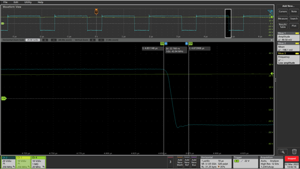
Falling edge with +5A output current.
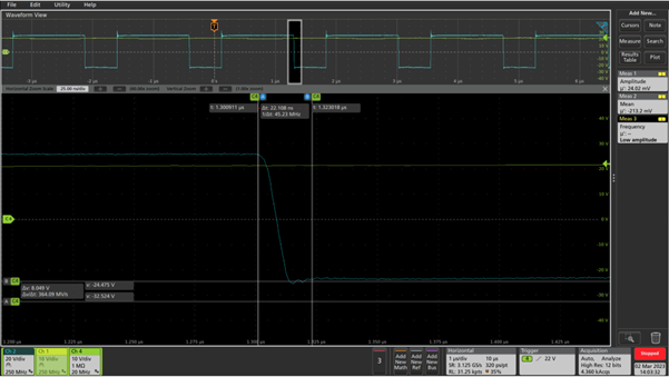
And now with schottkies added. Note that the undershoot has been reduced significantly
Audio Measurements
So, after trimming the output stage we turned to audio measurements with great expectations. To start with we were disappointed though, the THD vs power graph was unchanged in the GCOM modulator.
The conclusion is that the symmetric nonlinearity of the GCOM modulator is so dominant that the small improvement in commutation time isn´t visible in this graph. Later this fall we will dive into how to make the modulator even more linear so stay tuned.
Adding the audio band loop
So, the expectation now was that the complete amplifier would also measure the same since the GCOM stage measured the same. As a reminder, this is what the final MOSFET version could do.
THD vs power for the GaN amp
And this is how the GaN-amp performs when Schottkies have been added and the dead time and switching frequency has been adjusted. Notice that the colors have been swapped compared to the previous graph as we didn´t include 100Hz.
So, it performs basically the same as the MOSFET-version except for the slightly lower dip at 6.67kHz.
IMD
The IMD performance showed something interesting though. The 1kHz component has been significantly decreased, basically dropping into the noise floor.
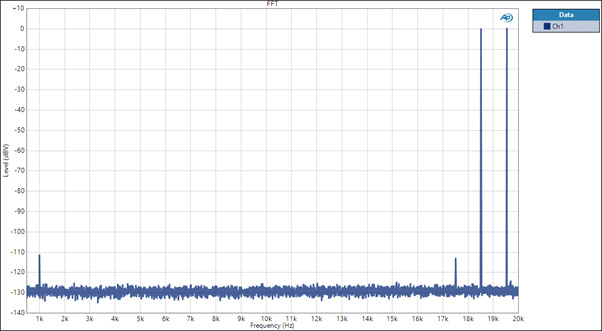
MOSFETs
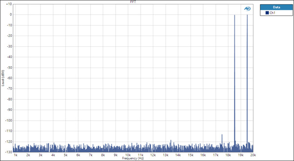
GaN
THD vs frequency
Even though you can argue that the human ear is more susceptible to harmonic distortion occurring in the frequency range where our vocal cords can produce sounds, it will always be our goal for our amplifiers to have the same characteristics in the entire audible range. As you can see, we have certainly achieved that with this amplifier.
Efficiency comparison
The reason why class d amplifiers were introduced in the first place was because of the gain in efficiency. Less losses means less cooling means less weight and size and for roadies that carry around 100kW of amps up and down stairs twice per day it can make a significant difference. It is of course also beneficial in terms of reducing energy consumption and the material usage.
So, the audio performance is slightly better with GaN compared to with MOSFETs. But how about the efficiency? We are now comparing amplifiers that switch at 650kHz which is quite high compared to most and not optimal for efficiency. The ripple current is also high as the output filter inductance has been reduced to allow for the high fsw and this leads to higher resistive losses everywhere. The high fsw also means more energy to drive the gates.
We also stop the modulation at around 87% to allow for more loop gain and this means we need 13% higher rails to generate the same output power, again leading to more losses. In an amplifier that modulates all the way to 100% and with a switching frequency of 400kHz, an efficiency of >95% is quite straight forward to achieve. But here, we pay for the performance with a few watts of losses.
GaN vs MOSFETs in the Conductor
At idle, the difference in consumption is the highest with the MOSFET-amp idling at 3.95W and the GaN at 3.18W. This is including the gate drive power consumption.
As you can see the MOSFET amp looks to have higher efficiency at low powers. Let´s zoom in.
Let’s zoom in
Now why is that? The explanation came to us quickly, as we had to turn down the dead time in the GaN-amp to avoid the high nonlinearity caused by the large commutation variation and this causes the output stage to hard switch slightly even at idle. The MOSFET-version has zero voltage turn-ON during the lower output powers which gives it lower losses.
At high power the GaN version reaches over 96.5% and the MOSFET version 95.5% i.e. one percent unit lower. This is not bad for a MOSFET amp switching at 650kHz.
Combining a very high efficiency with very good audio performance is very alluring for an engineer. It is proof that one masters it all. But there is always an efficiency penalty when trying to push up the audio performance, so it is interesting to see how much that is. How high is the efficiency of a MOSFET amp that switches at a lower frequency, like 400kHz and that modulates all the way to 100%?
This is what our Engine-400 does, so let´s have a look at its efficiency. We turned down the rails by 10% compared to the Conductor to take advantage of the 100% modulation depth.
Engine-400 Efficiency
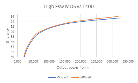
The Engine-400 efficiency is close to what the Conductor with GaN can do and 0.8 percent units higher than the Conductor with MOSFETs.
So, what is the efficiency penalty for having a pre clipper? It is easily tested by turning up the rails again and generating the same power with the Engine-400.
Engine-400 efficiency

Engine-400 efficiency
One percent unit
This means that if the MOSFET version of the Conductor did not have a pre clipper it would have the same efficiency as the Engine-400 despite the high Fsw. This is due to the state-of-the-art MOSFETs and the attention that has been paid to the inductor design. And if the GaN version of the Conductor did not have a pre clipper it would have an expected efficiency above 97%.
Conclusion
This was a few comparisons, more can be done at different frequencies, output powers and modulation depths and with different power devices. But it kind of makes sense to compare at a high fsw since GaN should be pretty good at that. The results show slight improvements in audio performance and about 1% better efficiency when using GaN but most importantly the idle consumption is 20% lower and when this is combined with the efficiency of a switch mode power supply it will be more like 40%. This is the biggest advantage as most amps usually run close to idle so if we want to make an impact on power consumption, this is the state to focus on.
But the improvements are not for free. The cost up is significant due to the high price for the GaN-switch itself, the more advanced gate drive circuitry, and the more complex protection circuitry. To some extent this can be compensated for though by less need for cooling and a less traumatizing electricity bill. In addition to that, the availability and supply of suitable GaN-switches is still limited compared to MOSFETs.
Is GaN worth it? That will be up to the customer (you) to decide, we can certainly make them.
Don’t hesitate to reach out!
If you want to know more ICEpower and the audio capabilities or if you have technical questions? Don’t hesitate to reach out.
If you’re looking to learn more about our technical capabilities and have questions, we encourage you to reach out to us. Our team is always ready to answer any questions you may have and provide you with the information you need to make informed decisions.
