The Hunt for Better Audio Performance
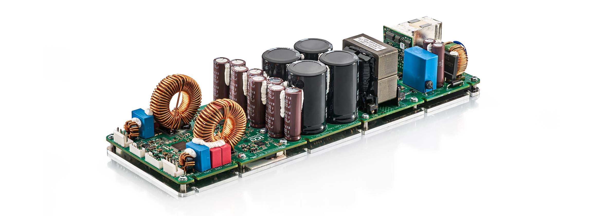
There is no denying, as an engineer you always want to make things better and better. This is what drives us to become engineers, right? As an amplifier designer you can focus on making smaller amps, cheaper amps, more robust amps, higher efficiency amps etc. But one of the most fun characteristics to focus on is the audio performance and since we in our daily work always work on the former(s), we set out to focus on the latter.
Learn More
What is the purpose of an Audio Power Amplifier?
For us at ICEpower, it is to be a perfect voltage controlled voltage source (Vout=k*Vin) within the audio band. This means it should always have the same gain, at small signals and at large signals, at low dV/dT and at high dV/dT. It should also have very low noise and very low output impedance.
The result will be an inaudible amplifier that lets the loudspeaker create the sound that the user desires. Of course, we will never reach a perfectly linear amplifier, but we will keep trying.

ICEpower Audio Amplifiers
Our amplifiers consist of a self oscillating class d modulator and another stage that basically identifies the errors that the modulator does in the audio band and acts to correct them. There are always limits to how much gain (force) we can give the correction stage, while maintaining stability so it is very important to make the modulator as linear as possible to start with. But the gain we give the correction stage can be larger if the delay in the modulator is smaller.
The idea we got was to move the resonant frequency (fc) of the output filter as far up as possible in order to be able to add as much loop gain as possible in the audio band without risking the two to meet and make a mess. But the prerequisite was to maintain the same linearity and attenuation of the PWM pulse train as with a lower fc so that the added gain in the audio band would actually do some good on the end result. We also did not want to reduce the output filter cap as that would reduce the Q but by instead decreasing the output filter inductance and use high end ferrite material with carefully applied litz windings an output filter Fc of 70kHz with a >700kHz self oscillation frequency, could be achieved. The class d core we choose is the GCOM (globally controlled oscillation modulator). As long as the modulator comparator is well designed, the GCOM can achieve a large closed loop bandwidth which is basically load independent while also achieving quite good audio performance. The load independent gain is a crucial parameter when adding the audio band loop gain as it makes the error correction force easier to control during all speaker loads, but more on that topic further down. GCOM also has all its gain around the output filter which means it has a much better control of the resonance of the output filter, which is usually problematic in an unloaded condition (or with inductive load).
Great Audio Perfomance
The class d core we choose is the GCOM (globally controlled oscillation modulator). As long as the modulator comparator is well designed, the GCOM can achieve a large closed-loop bandwidth which is basically load independent, while also achieving quite good audio performance.
The first results
Increasing the switching frequency up to >700kHz would have been difficult two decades ago, when class d was still an infant, but MOSFETs are getting better and better all the time. Output charges and Miller charges are getting lower and lower and the body diode is also behaving more and more like a fast rectifier diode with efficiency gains during hard switching as a result. The lower charges makes it easier to switch faster and if the layout is well designed the snubber energy consumption can be kept low enough to allow for quite a fast self commutation which allows for a shorter dead time without increasing the idle consumption. This shorter dead time is necessary when the switching frequency is increased, otherwise the time in the “dead region” will be a larger part of the period which leads to larger non linearities.
With our ICC4 gate driver, we can tune the dead time as we desire and the propagation delay is a short 25ns which allows for a self-oscillating modulator with high fsw.
After spending a lot of time on the modulator itself, we have achieved this performance.
GCOM Stage Frequency response
So here we are, with a GCOM stage having a large 140kHz closed loop bandwidth and a THD vs power graph that is a good start.
What to do next?
Adding a biquad filter
Next step: Adding a biquad filter to the modulator will linearize it while not changing the behavior seen from the outside much at all. As it increases the open loop gain from just above 100 times, to ten times of that, it makes the closed loop gain of the modulator match the gain set by the resistors for a non inverting gain stage. That takes us to the following state.
Frequency Response with Biquad
Frequency response of GCOM including biquad filter
The result, we call it the Conductor…
As can be seen, it is quite obvious that the biquad filter lets go of the modulator around 30kHz where it falls back to where it was before.
So now we will start adding integrators to the audio band.
It is always difficult to add gain in the audio band while maintaining a nice and flat closed loop frequency response. It gets even more difficult when you do it with higher order integrators. But after spending many months of experimenting, thinking and testing, we managed to create a topology that was able to maximize the gain in the audio band, having the same loop gain at 5kHz as at 20kHz (we always add a little more below that to handle power supply non idealities). The result, we call it the Conductor, as it controls the crowd of components with a firm hand (ohh, give me a break!, it has to be called something!). And you can also choose to think that we mean that the end result is an electrical “conductor with gain”. The Conductor is a nested negative feedback system with two integrator stages, where both stages takes feedback from the output of the amplifier. Leads, poles and zeroes are selected so that each stage as far as possible only works to correct the errors, not the absolute gain of the modulator which by itself is a very smooth first order slope.
THD vs power graph of complete Conductor amplifier
The distortion is now very low, almost reaching the noise floor of the APx555 and it is basically flat through the audio band. The same of course goes for IMD.
Very Low Distortion
Noise is mainly determined by other factors than loop gain. Having lower resistance values and better OPAMPs is necessary and setting the gain very low is a trick that can be used to display very low noise figures.
IMD Graph
Basically, as the maximum peak output voltage is 50V and the OPAMP supplies are +/-12V, the gain could be set as low as 5 times. But DACs that can generate 10Vpk are unobtainium so somewhere in the chain, 3 times more gain is needed. We set the gain to 26.2dB in order to make it usable with obtainable signal sources. But still, the noise is around 30uVrms unweighted and 18uVrms A-weighted.
100kHz bandwidth
We would have loved the frequency response to be a smooth first order slope with a -3dB at 100kHz+ but we still have some work to do. A first order would mean the phase shift doubles as the frequency doubles i.e. the amp has the same propagation delay at all frequencies and that is very desirable. But this is something we haven´t solved yet (we are working on ideas though).
As of now, we are somewhere in between a first and second order and there is as you can see also a little 0.2dB glitch at 45kHz where the audio band loop hands over to the modulator. This is hence not the filter resonance (which is located at 70kHz). The bandwidth is large enough though with -0.1dB @ 20kHz and -3dB @ 120kHz.
And yes, it is stable.

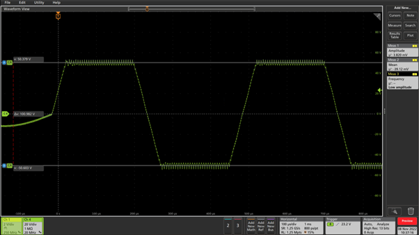
Heavy clipping @2kHz without load

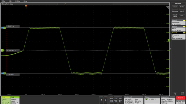
Heavy clipping @2kHz with 4R load
Don’t hesitate to reach out!
If you want to know more ICEpower and the audio capabilities or if you have technical questions? Don’t hesitate to reach out.
If you’re looking to learn more about our technical capabilities and have questions, we encourage you to reach out to us. Our team is always ready to answer any questions you may have and provide you with the information you need to make informed decisions.
